
EMBEDDED CONTROL
N50
1-channel Board-type
PID Temperature Controller
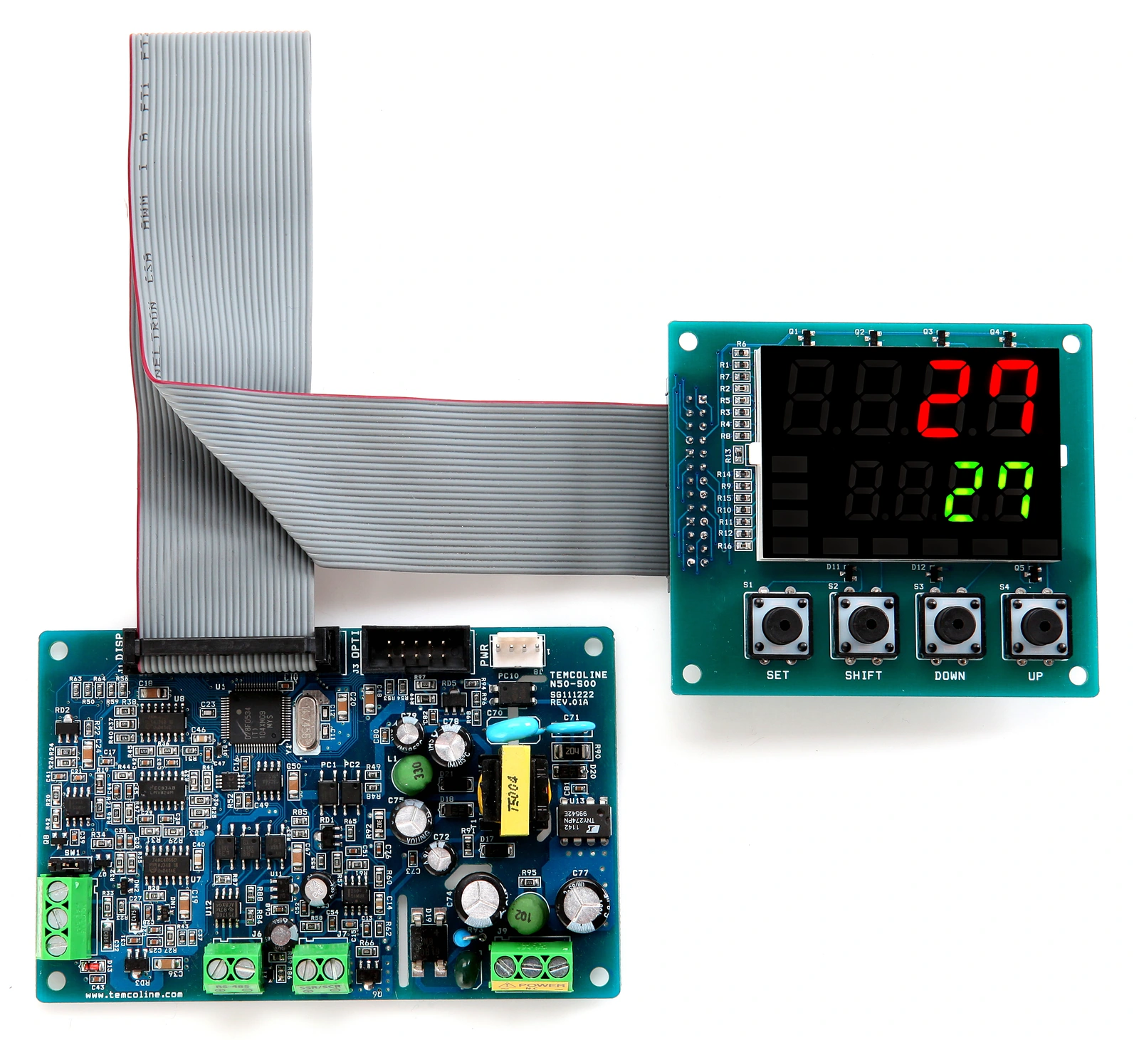
Efficient use of space.
Precise control.
T50 control technology in an embedded control board.
SG-PID control
Variable sampling: 50~250 ms
RS-485 communication
Isolated communication port
Separate display
Flexible installation in equipment


A board designed to fit inside your equipment
to help save space and optimize system costs.
 Manuals Library
 Product Inquiry
01Features
SG-PID control
Supports Super 2-degree-of-freedom PID, Fast, Auto-Tuning and simultaneous heating/cooling control.
Universal I/O
Supports 24 input types and 4 output types, including TC, RTD, voltage and current inputs.
RS-485 communication
A fully isolated communication port supports Modbus ASCII/RTU and PC/TL-Link.
Flexible operating modes
Configure run/stop, manual control and ramp control modes to suit operating conditions.
SYNC communication
Sync-Master/Slave settings enable synchronized communication with up to 250 units.
8-segment input correction
Eight-segment input correction helps reduce deviations caused by the control environment.
Limit controller mode
Supports monitoring-only mode and stores the peak value when an alarm occurs.
Temperature recording and management
Remote monitoring and data viewer software is included as standard.


Optional features
The following features are optional.
Heater burnout alarm (HBA)
CT current monitoring and accumulated heater operating time help estimate heater service life.
Alarm and event outputs
Supports 20 alarm/event types, up to 3 output points, output-port reassignment and AND/OR logic.

02Specifications
| General | |
|---|---|
| Model | N50 |
| Number of channels | 1 channel |
| Supply voltage | 100~240 V AC, 50/60 Hz |
| Allowable voltage range | 85~265 V AC |
| Optional power supply | Rated: 24 V AC/DC / Permissible range: 20~28 V AC/DC |
| Power consumption | 8 VA maximum |
| Input and measurement | |
| Thermocouple (TC) input | K, J, T, E, R, B, S, L, N, U, C(W5), D(W3) |
| RTD input | KPt100(KS), JPt100(JIS), Pt100(DIN) |
| Analog current input | 4~20 mA DC |
| Analog voltage input | 1~5 V DC, −10~20 mV DC, 0~100 mV DC |
| Measurement accuracy | ±0.3% of FS + 1 digit |
| Input impedance | Current input: 250 Ω / Voltage input (including TC): at least 1 MΩ RTD lead resistance: 10 Ω or less, with equal resistance in all three leads of a 3-wire connection |
| Input sampling period | 50~250 ms (variable according to the SG-PID algorithm) |
| Control and output | |
| Control methods | Super 2-degree-of-freedom PID (SG-PID algorithm), Fast, Auto-Tuning |
| Relay output | 1 changeover contact, 250 V AC, 3 A (resistive load) Electrical life: at least 100,000 operations / Time-proportional PID or ON/OFF output |
| Voltage (SSR) output | 15 V DC, 25 mA (built-in short-circuit protection) Voltage pulse / Time-proportional PID output |
| Current (SCR) output | 4~20 mA DC / Permissible load impedance: 600 Ω or less / Continuous PID output |
| Communication | |
| Communication interface | Fully isolated 2-wire RS-485 |
| Maximum communication speed | 19,200 bps |
| Maximum connections | 99 units (32 units recommended) |
| Supported protocols | PC/TL-Link, Modbus ASCII·RTU, Sync-Master/Slave |
| Optional features | |
| Heater burnout alarm (HBA) | CT current monitoring / Accumulated heater operating time (service-life estimation) |
| Alarm and event outputs | 20 alarm/event types / Up to 3 output points / Output-port reassignment and AND/OR logic |
| Environment and dimensions | |
| Ambient temperature | −10~50 °C |
| Ambient humidity | 25~85% RH (no condensation or freezing) |
| Weight | Main board: 60 g / Display board: 35 g / Connecting cable: 24 g |
| Main board dimensions and mounting | Board: 110 × 70 mm / Mounting-hole spacing: 102 × 62 mm / 4-Ø3.5 mm |
| Display board dimensions and mounting | Board: 80 × 70 mm / Mounting-hole spacing: 72 × 62 mm / 4-Ø3.5 mm |
03Dimensions & Wiring
Select a drawing to zoom in, or open the original vector PDF.
N50 dimensions
Vector PDF ↗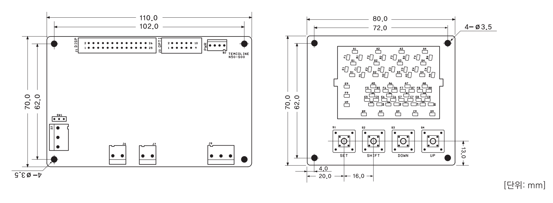 Enlarge drawing
N50 input, output and power wiring
Vector PDF ↗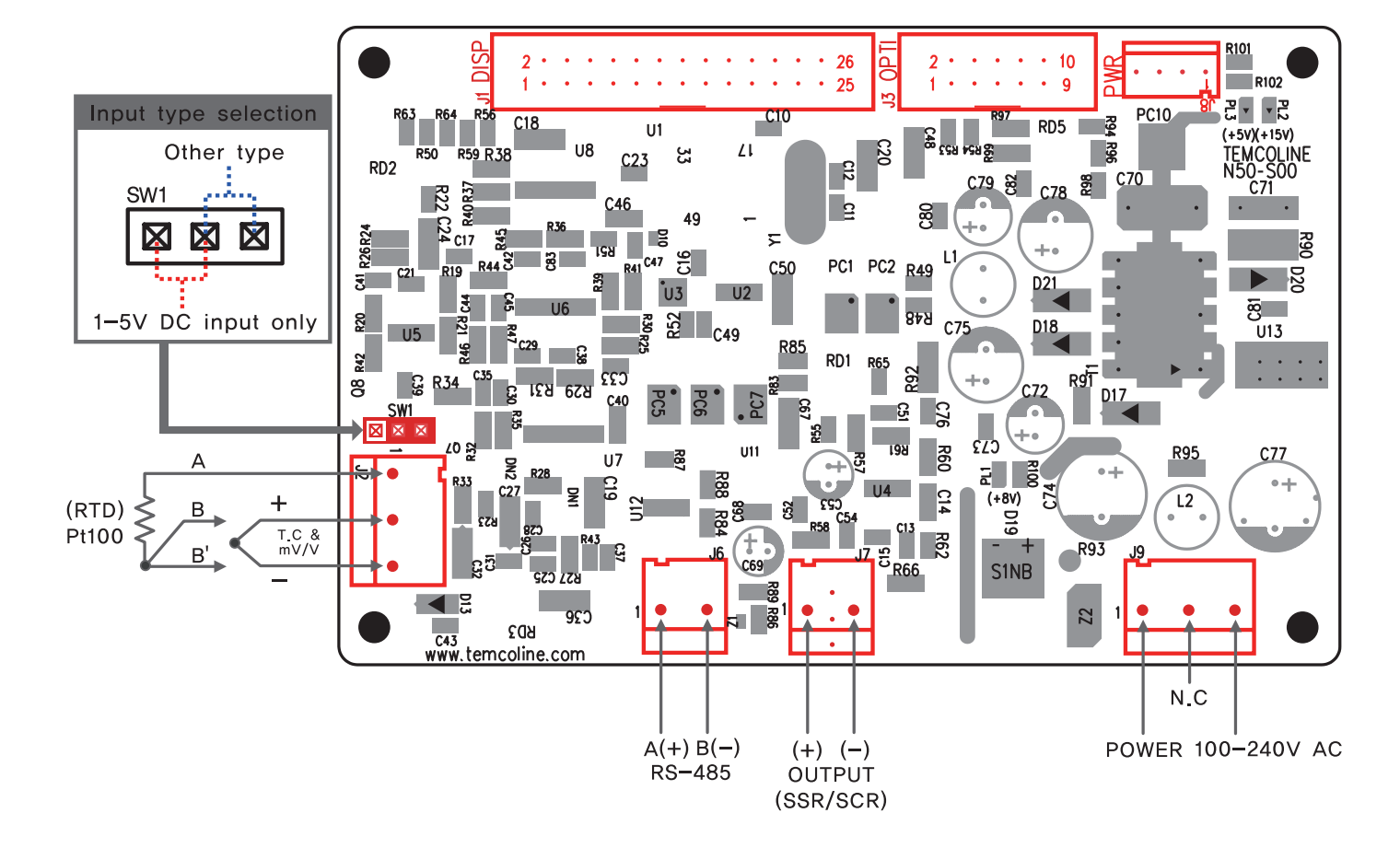 Enlarge drawing
Check the power supply and I/O configuration against your product's selected options. The wiring diagram shows the switch setting for 1~5 V DC input.


