
EMBEDDED CONTROL
N74
4-channel Board-type
PID Temperature Controller
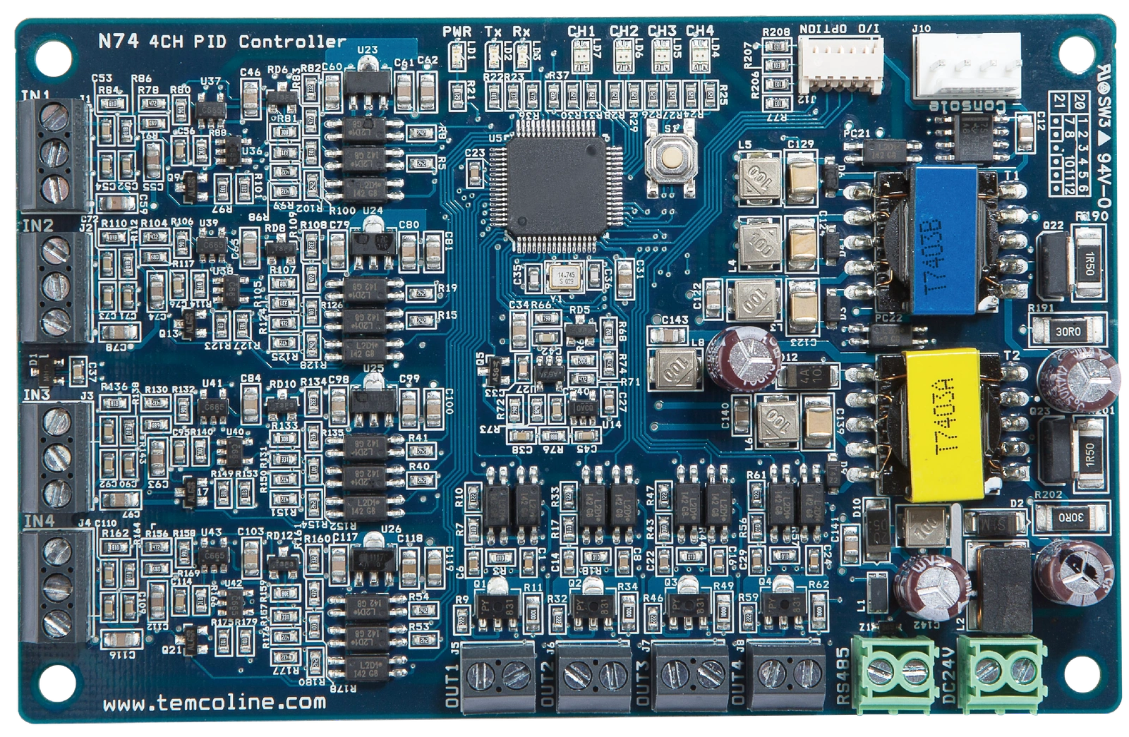
Efficient use of space.
Precise control.
M74 control technology in an embedded control board.
4-channel control
Multiple control channels on one board
SG-PID control
Super 2-DOF PID
RS-485 communication
Connect to external systems


A board designed to fit inside your equipment
to help save space and optimize system costs.
 Manuals Library
 Product Inquiry
01Features
Embedded board design
Integrates M74 control technology on a single board for efficient installation inside equipment.
4-channel control
Supports TC, RTD, voltage and current inputs to control multiple temperature points on one board.
SG-PID control
Super 2-degree-of-freedom PID and variable sampling control accommodate a range of operating conditions.
RS-485 connectivity
Connects to external devices via Modbus ASCII/RTU, PC-Link or TL-Link.
Input/output isolation
Provides isolation between input terminals, between input and output terminals, and between input and power terminals.
D74C console support
Add a D74C control and display console for standalone operation without communication with a host system.


Same dimensions and mounting holes as N50
The board dimensions and mounting-hole positions match N50, allowing the existing mounting structure to be used.
This describes mechanical compatibility. Check each model's specifications for power supply, wiring and control configuration.02Specifications
| General | |
|---|---|
| Model | N74 |
| Number of channels | 4-channel control I/O |
| Supply voltage | 24 V DC, Class 2 |
| Allowable voltage range | 90–110% of rated supply voltage |
| Power consumption | 5 W max. (at maximum load) |
| Display & operation | No built-in display. Set parameters and monitor/control operation from an external device, such as a dedicated console, touch panel, PC or PLC. |
| Input and measurement | |
| Thermocouple (TC) input | K(CA), J(IC), E(CR), T(CC), R(PR), B(PR), S(PR), L(IC), N(NN), U(CC), C(W5), D(W3) |
| RTD input | KPt100(KS), JPt100(JIS), Pt100(DIN) Permissible lead resistance: 10 Ω or less, with equal resistance in all three leads of a 3-wire connection |
| Analog voltage input | 0~5 V, 1~5 V, 0~10 V, 0~100 mV, −10~20 mV |
| Analog current input | 4~20 mA |
| Sampling period | Minimum 50 ms (simultaneous variable sampling control of 4 channels) |
| Measurement accuracy | ±0.3% of FS + 1 digit |
| Control and output | |
| Control methods | Heating, cooling, or simultaneous heating/cooling control ON/OFF, P, PI or PID control (Super 2-degree-of-freedom) |
| Retransmission output (RET) | 4~20 mA DC; load resistance: 500 Ω or less (effective resolution: 1/6000) |
| SSR voltage pulse output | 12 V DC, 25 mA (built-in short-circuit protection) Time-proportional PID output or ON/OFF control |
| SCR current output | 4~20 mA DC or 0~20 mA DC (load resistance: 500 Ω or less) |
| Proportional band (P) | TC/RTD: 0.1~999.9 °C Analog voltage/current input: 0.1~999.9 digit |
| Integral time (I) | 0~3600 s |
| Derivative time (D) | 0~3600 s |
| Control output cycle (Ct) | SSR mode: 0.1~100 s / Relay mode: 1~100 s |
| Communication | |
| Host communication | RS-485 / Modbus ASCII/RTU, PC-Link or TL-Link Communication speed: 9,600~115,200 bps |
| PC Loader communication | Console (dedicated display controller), USB interface cable (optional) |
| Insulation and reliability | |
| EEPROM endurance & retention | At least 4 million write cycles / Data retention: at least 200 years |
| Insulation resistance | 100 MΩ min. (500 V DC insulation tester) |
| Insulation construction | Double or reinforced insulation Dielectric strength between measurement input and power supply: at least 1 kV |
| Dielectric strength | 1,000 V AC, 50/60 Hz for 1 minute Between input terminals, between input and output terminals, and between input and power terminals |
| Vibration resistance | 5–55 Hz (1-minute cycle), 0.75 mm double amplitude / 2 hours each in X, Y and Z directions |
| Noise immunity | Square-wave noise from a noise simulator / 1 μs pulse width, ±1 kV |
| Environment and dimensions | |
| Ambient temperature | Operating: −10~50 °C / Storage: −20~60 °C |
| Ambient humidity | Operating: 35~85% RH / Storage: 35~85% RH |
| Weight | 110 g total (unit: 60 g) |
| Dimensions and mounting | Board: 110 × 70 mm / Mounting-hole spacing: 102 × 62 mm / 4-Ø3.50 mm |
03Dimensions & Wiring
Select a drawing to zoom in, or open the original vector PDF.
N74 dimensions
Vector PDF ↗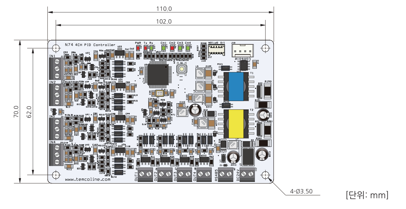 Enlarge drawing
N74 input, output and power wiring
Vector PDF ↗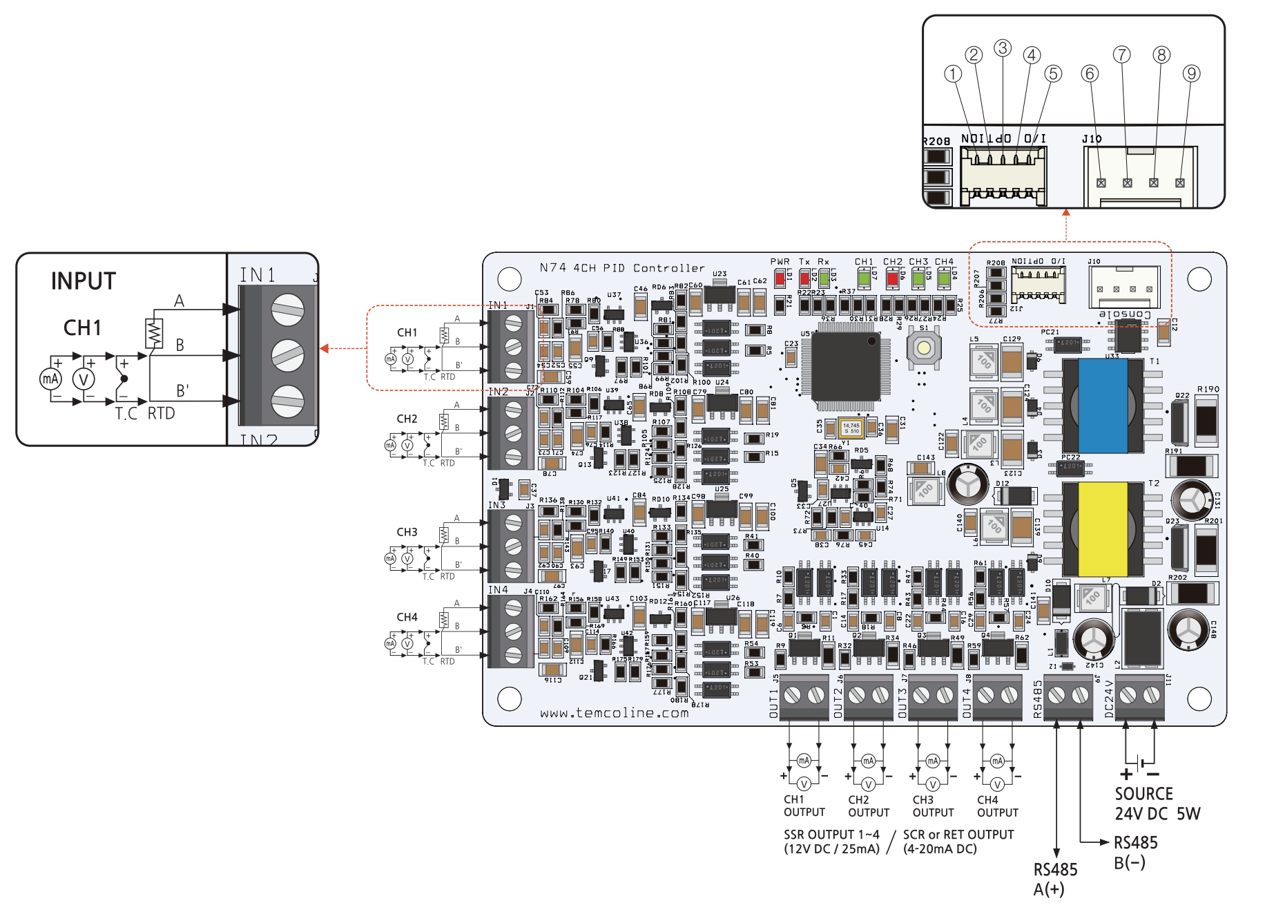 Enlarge drawing
J12 connector Optional I/O
Digital I/O and option-card interface
- CH1 alarm relay control output or option-card interface pin
- CH2 alarm relay control output or option-card interface pin
- CH3 alarm relay control output or option-card interface pin
- CH4 alarm relay control output or option-card interface pin
- GND
J10 connector Console and loader
Dedicated display or loader interface
- Console power output (+24 V DC)
- RS485 RTX + pin
- RS485 RTX − pin
- Console power output (0 V/GND)


